
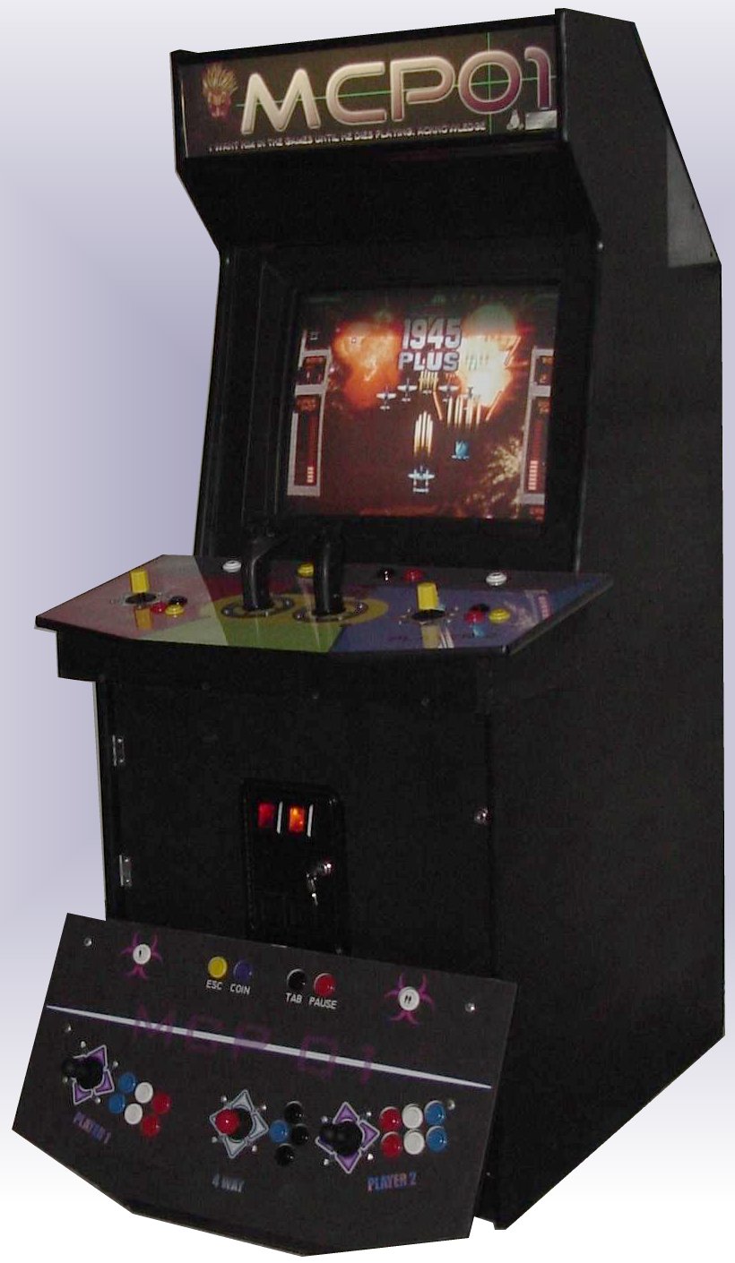
LINUX - MASTER CONTROL PROGRAM 01 (MCP01)
A Quest For Instant Gratification (drawn out over several months)
|
Saturday, Jan 24 2003: MAME 63 Patch for Rotary (SNK joy) games!
SNK L30 Rotary patches updated for MAME 63! (Thanks Jerry Janis!)
to play with. unzip these into your $MAMESRC/src directory (with -d flag) and
recompile.. In each Rotary game, set BUTTON 4 to input for LEFT rotation and
BUTTON 5 to input for RIGHT rotation. Have fun!
download/rotfix63v1.zip
|
|
Saturday, May 11 2002: MAME 59 Patch for Rotary (SNK joy) games!
I've been getting lots of requests for the patches that I did to change MAME input scheme
for SNK rotary games... Well, this is the ugly, but functional version for everyone
to play with. unzip these into your $MAMESRC/src directory (with -d flag) and
recompile.. In each Rotary game, set BUTTON 4 to input for LEFT rotation and BUTTON 5
to input for RIGHT rotation. Have fun!
http://cryptnet1.net/files/rotfix59v1.zip
|
|
Wednesday, May 8 2002: What have you been DOING!?
Here's a relatively quick update on what I've been working on recently.
Basically, I've been working full tilt on restoring an old Tron Machine that
was non-working when I got it at the Dallas Super Auction (for $125). I was going
to just strip it for controls, but after messing around inside I managed to get
it working. Thus, I decided that I could not MORALLY strip a mostly working (but
water damaged cab) when I could easily restore it and put it back into circulation.
I don't have a full webpage on the restoration process yet
, however here are some pix of the progress.
http://cryptnet1.net/tron3/
|
|
Friday, Dec 14 2001: More work on Control Panel #2
I moved on from creating the template and overlay for the second control panel,
to actually constructing it. I had the main panel already cut out from my
initial stock (as shown in the
plans), so I only had to buy some more Plexi
(see mishap on Nov5). In
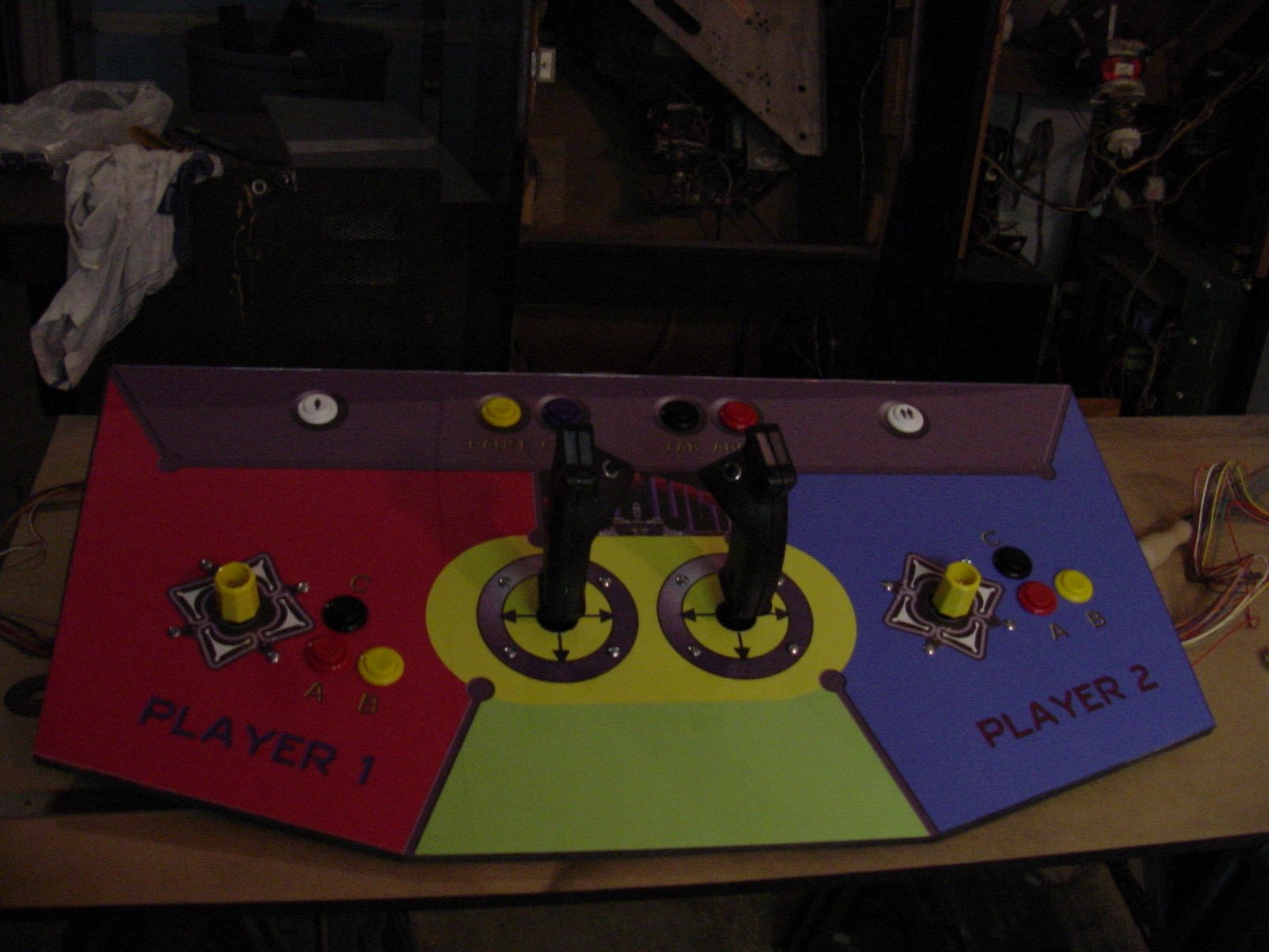
any case, work proceeded relatively swiftly up to and including mounting all
the pieces together. Only the wiring for the CP is left to be completed.
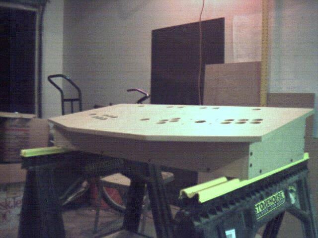
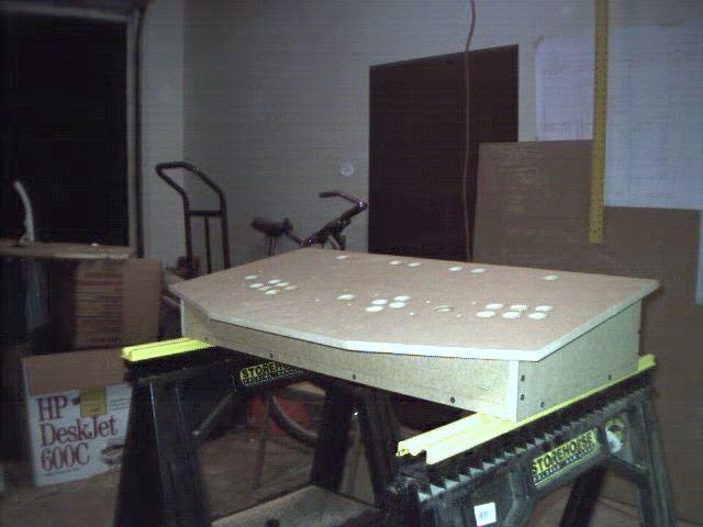
Here are some pics during CP2 construction
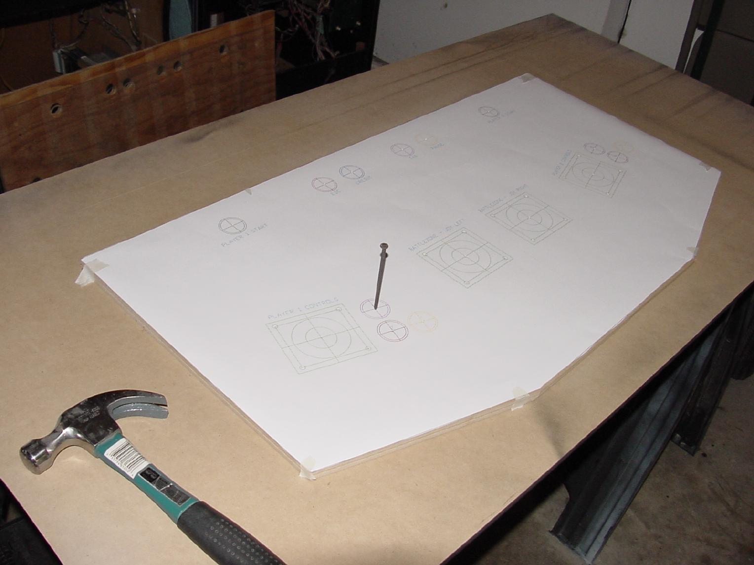
IMAGE: Control Panel 2 with template in place for scribing drill
locations
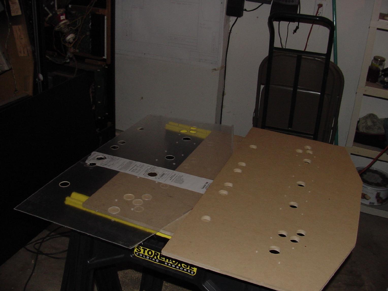
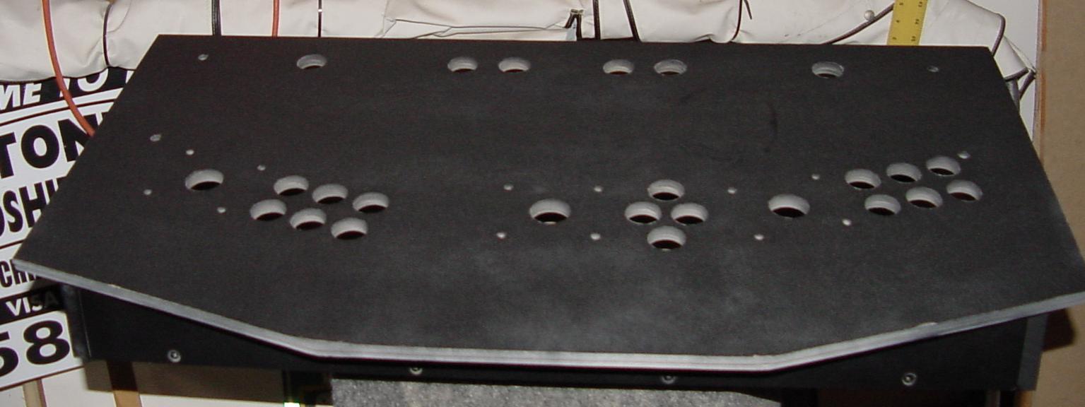
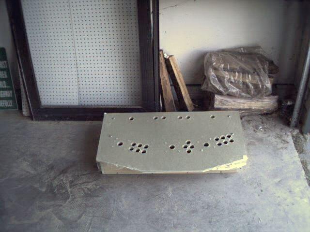
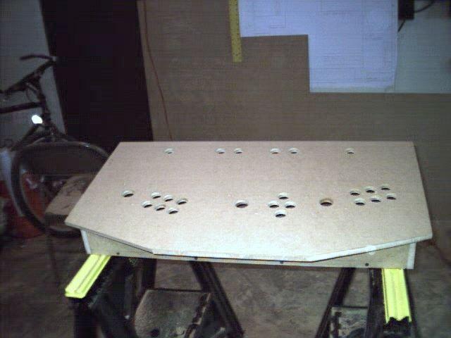
IMAGE: Control Panel 2 and plexi overlay with all holes drilled
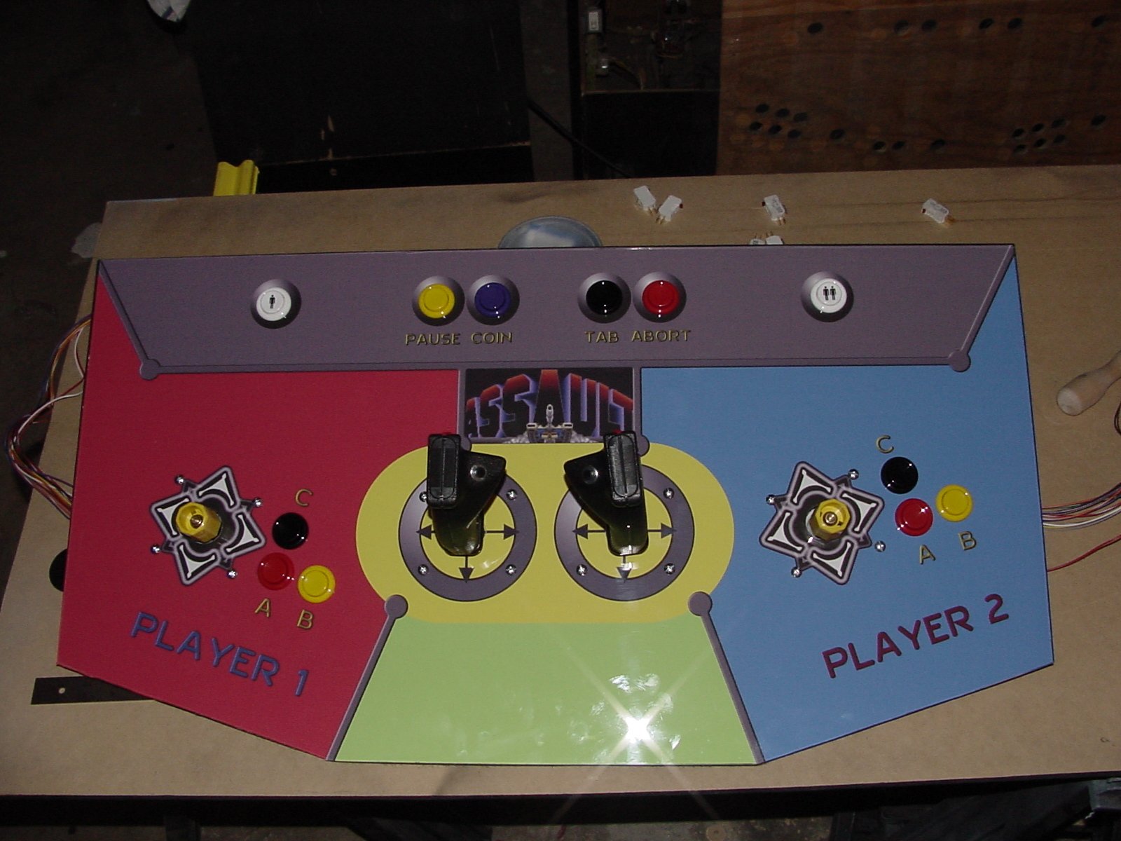
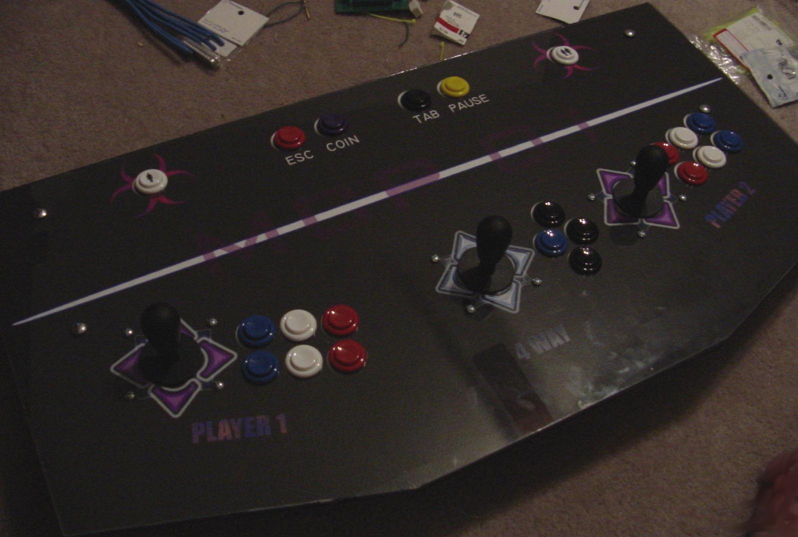
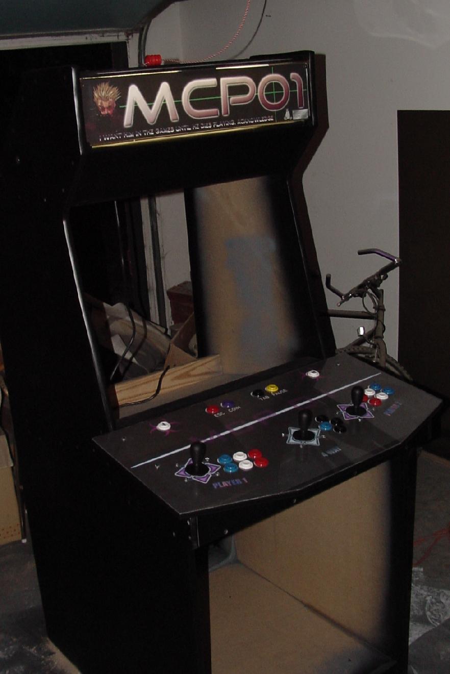
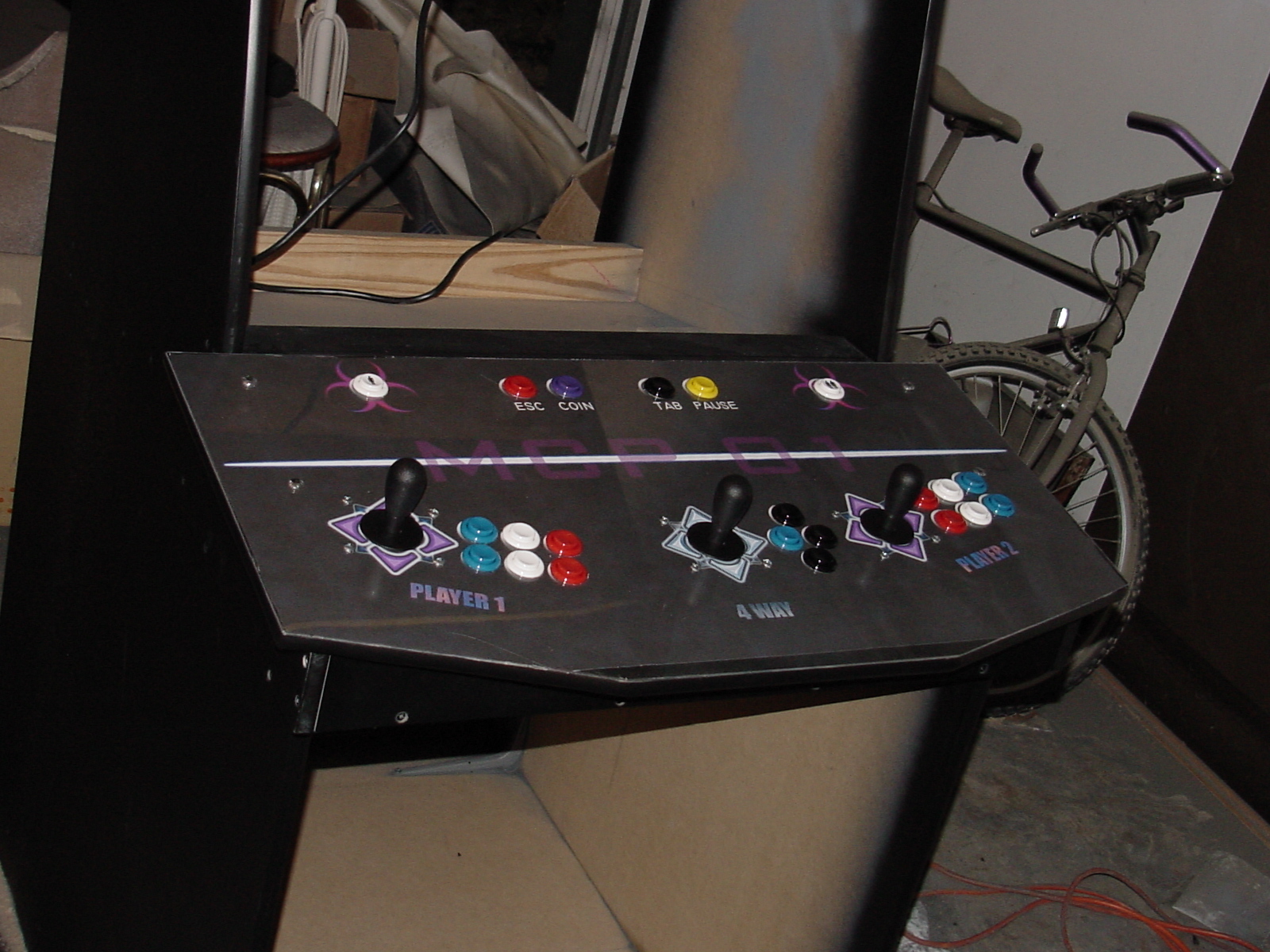
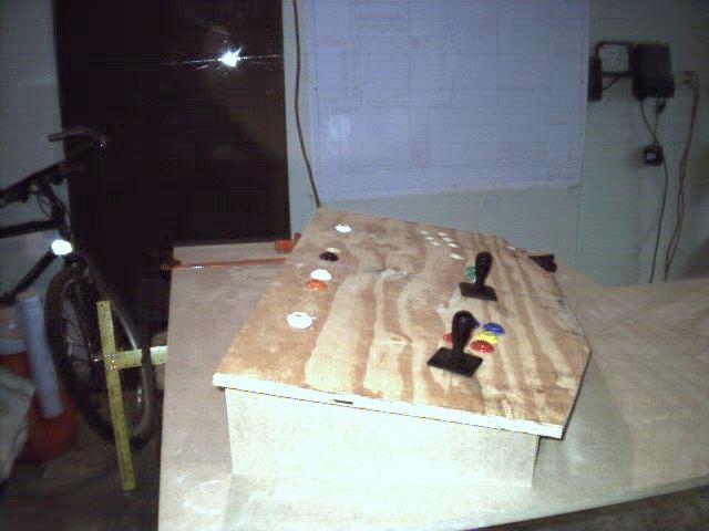
IMAGE (angle 1): Control Panel 2 complete (sans wiring)
IMAGE (angle 2): Control Panel 2 complete (sans wiring)
IMAGE: Miscellaneous shot of the Front End PLUS new HAPP monitor bezel
IMAGE: Another shot of the Front End without scanline on film
A few Misc Notes:
This time I took a bit more patience with the plexi and followed the tips on
THIS PAGE for
working with acrylic. Basically, I performed the following additional steps:
- Used a more professional quality scoring knife for the breaking stage
instead of the little cheap plastic job I had for the first one.
- Placed each edge of plexi with about 1/16" of overhang on a straight
board. and filed a smooth continuous (diagonal) stroke towards myself
several times, until the edge no longer had any ridges or dips
(from the breaking step). I used a 10 inch, 10 mil bastard cut file for
this.
- Ran a sharp edged metal ruler along the plexiglass edge at a 45 degree
angle to the top to take the sharp corner off as well as any burrs left over
from filing)
- I managed to get this far without scratching the plexi. If I had,
there is the option of putting the plexi in a partially filled bathtub
and gently sanding scratched area with 600 grit wet/dry sand paper.
I have yet to try this, but have heard that it works wonders on
scratched plexi
This resulted in a plexi overlay that looks and feels an order
of magnitude better than my first control panel. When this panel
is finished, I'm going to dismantle my first one and perform these steps
on it as well.
|
|
Tuesday, Nov 28 2001: Just a pic update
I've been negligent on posting my progress since i actually got
the cabinet to a playable standpoint (too busy doing software chores
[and PLAYING]) In any case, here are a some pictures (of various large
sizes). I'd estimate the cabinet is now 85% complete:
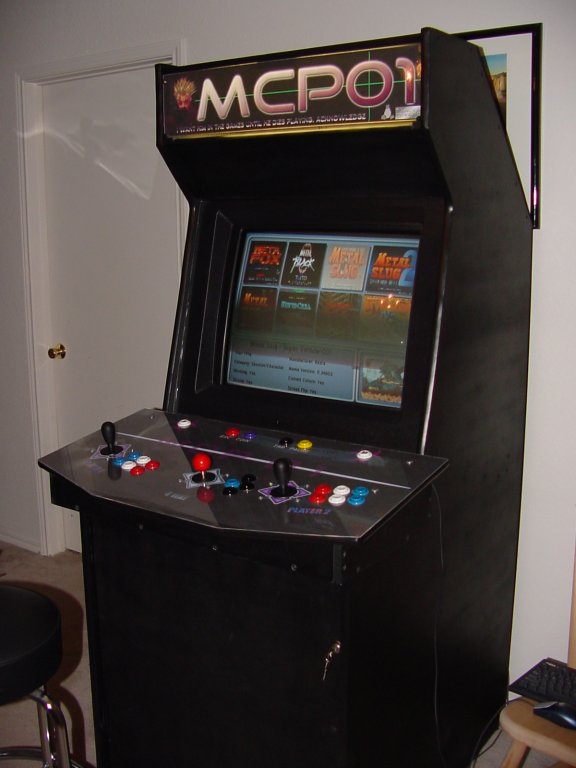
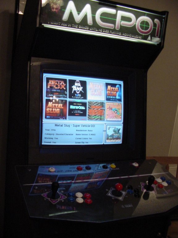
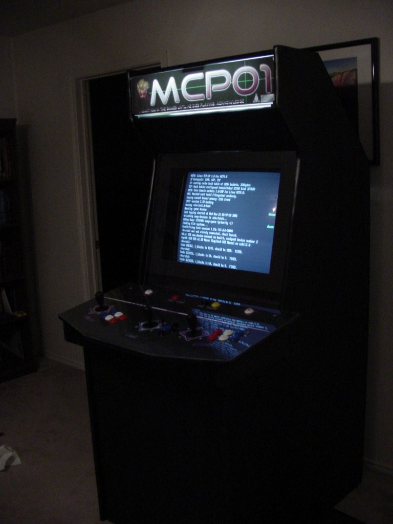
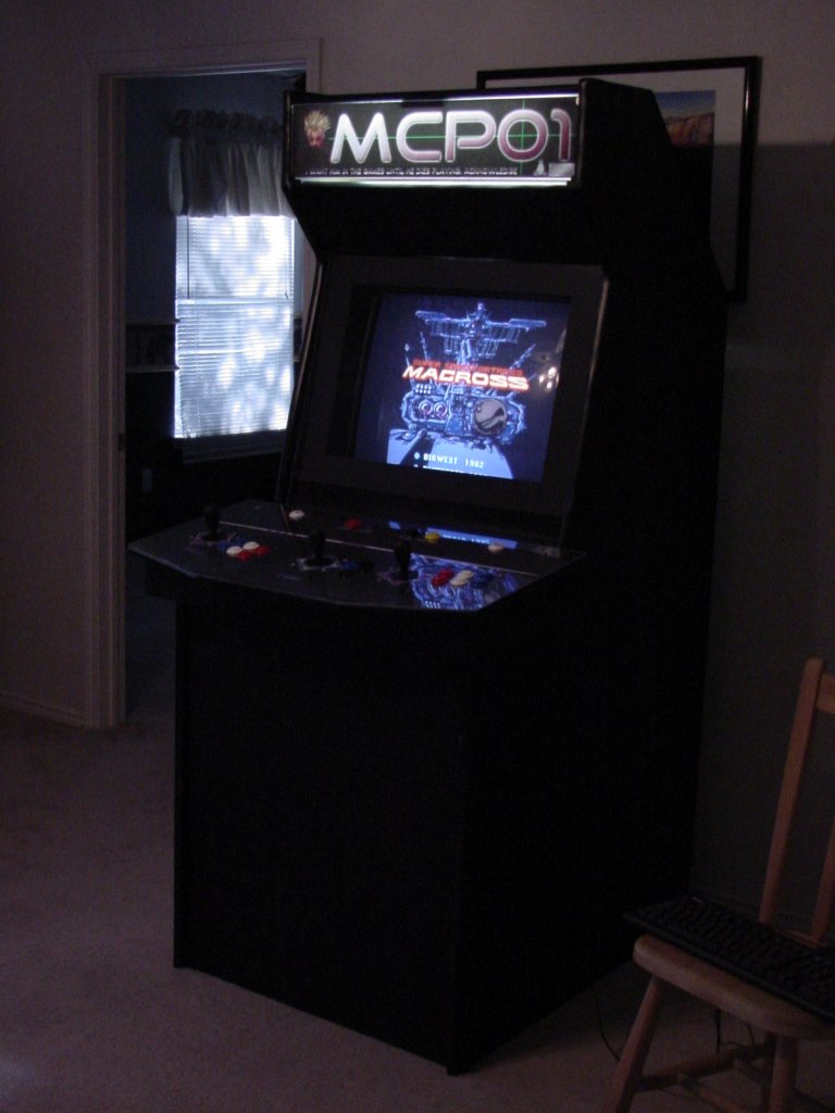
IMAGE: Isometric 1 showing SuSE linux boot screen
IMAGE: Isometric 2 showing Macross
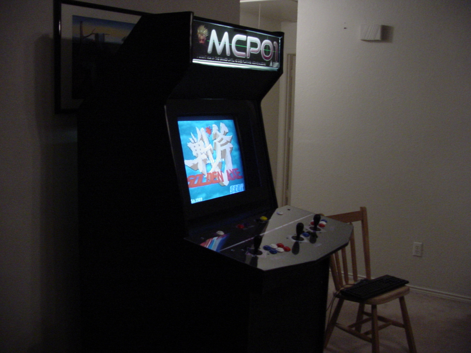
IMAGE: Golden Axe!
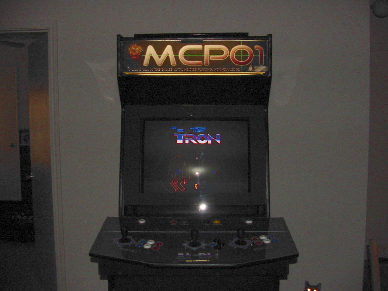
IMAGE: TRON (and my cat, p1x3l)
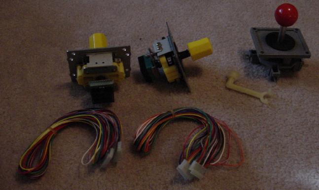
IMAGE: New Controls (Ikari and WICO leafswitch)
[ed: The WICO leafswitch in the last pic was used in the first control
panel as a replacement for the four way HAPP super. This gives a very authentic
feel, as it is the actual style of joys used in many original 4-way games)]
My current tasks have shifted towards working on Control Panel 2. It is a 2-player
Ikari Warriors Setup (with REAL SNK rotary joys) and a 1-Player
Assault/Battlezone setup. I will post the AutoCad design and overlay
when I complete them.
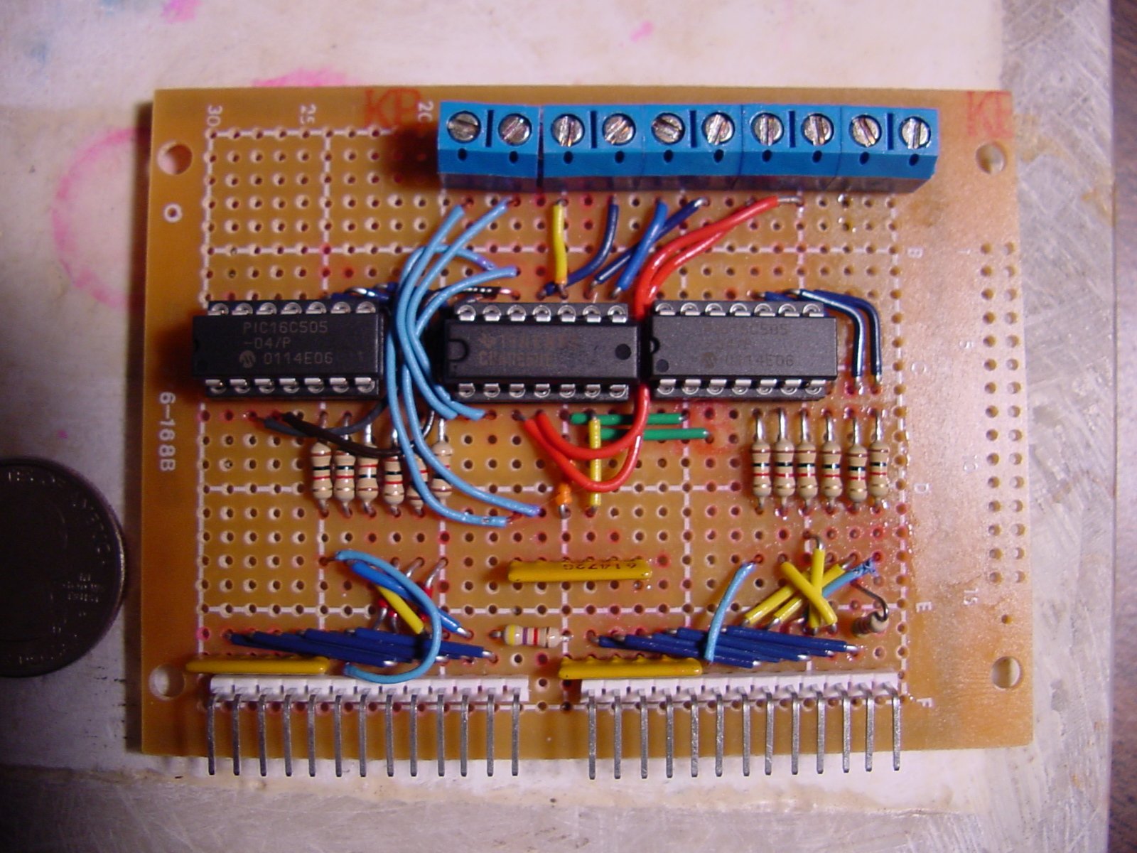
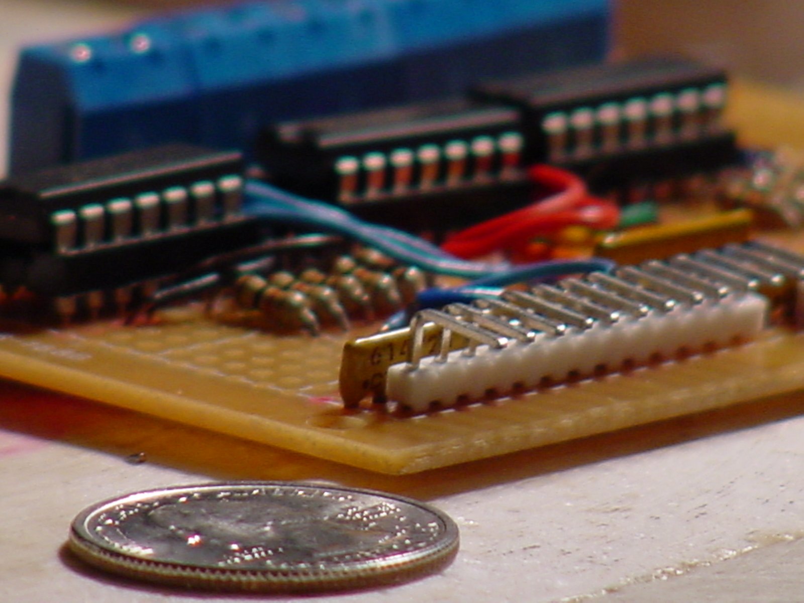
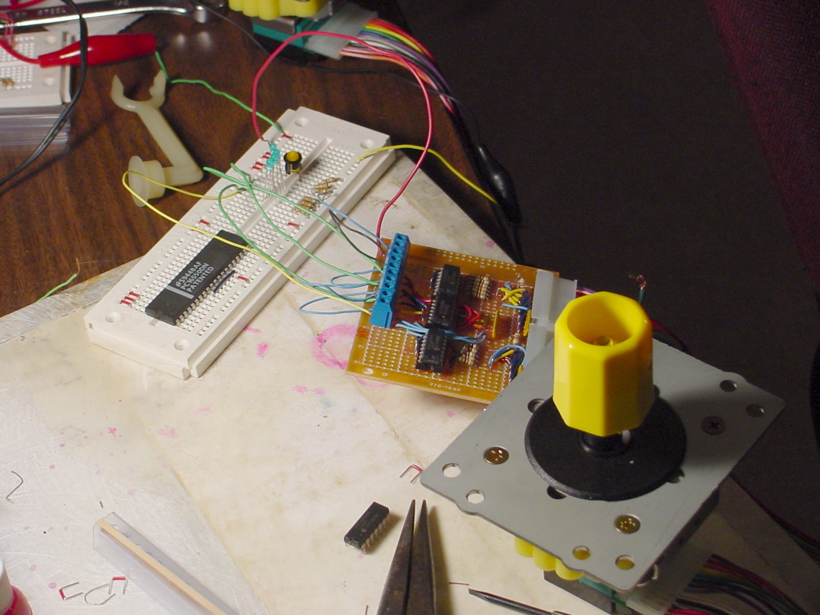
As for the PC interface for the Rotary Joys, they have a 13 pin
interface for the rotary switch. Rather than pumping those into
a parallel port or something similar to decode and pass to mame,
I've purchased some PIC (16C505) microcontrollers and a PIC
programmer and will be using
Druin's plans as a reference.
(Basically, I will convert the 13 pins positional output of the SNK
joys into Clockwise and Counterclockwise
Rotation signals that Mame use as button presses for rotating)
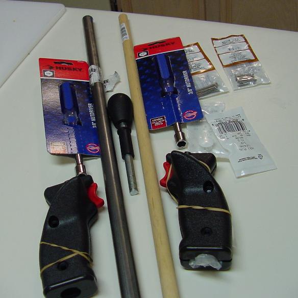
A Slight update on the Assault Joystick creation: When I cut the the nut drivers I bought
at the handle, I discovered they don't have a completely hollow shaft,
it's only hollow about half its length. I was counting on a hollow shaft so that I could
run the button wires through the middle. Now I'm in
search of some 3/8" OD [the diameter of a HAPP Super shaft] steel or
aluminum tubing.
|
|
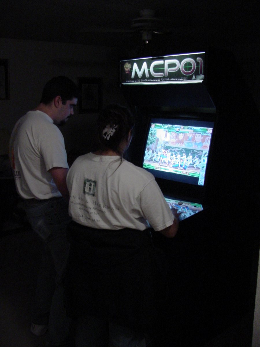
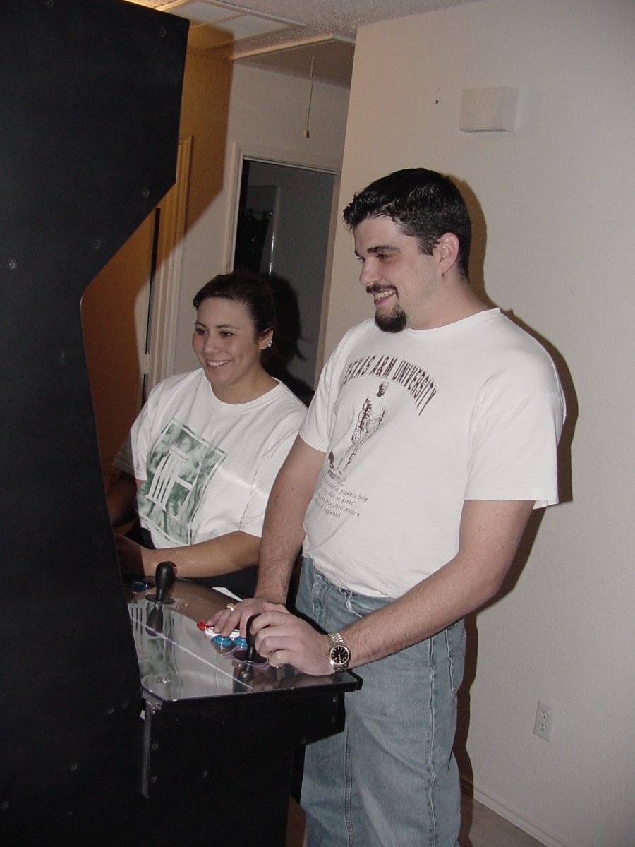
Monday, Nov 19 2001: Hey! Is that a light down there?
Tonight, I had some friends over to help me move the cabinet
upstairs before it grew even larger and heavier.
It was easier than I had expected, but it was still quite heavy (even without
the TV/Computer/Doors/etc...)
After playing a couple hours of Rogue Leader (Great game, BTW), The idea
was proposed to fire it up and test it out. So over the course of the next
20 minutes, we installed the computer/speakers/TV/control panel and
connected up all the wiring harnesses.... Let me just say,
I'm gonna have problems getting it FINISHED now!
IMAGE: IT LIVES!
IMAGE: The smiles alone were worth all the work (well and the cabinet)
Actually, I'm glad that we hooked it up. I found out there were a few little
wiring and configuration problems (which I've ironed out since they left)
There were also some problems I noticed on the placement of the encoder in the
box that only became apparent when the wires were plugged in.
Overall, however, I'm amazed that this went together so fluidly.
|
|
Saturday, Nov 17 2001: God is in the Details
Got a lot of pics for you today... After the paint dried on the cabinet,
I began to work on details:
|
|
Thursday, Nov 15 2001: Painting
Here are the accomplishments today:
- Removed controls and wiring harness from control panel 1
- Routed T-Molding groove for both control panel 1 and control panel 2
- Primed and painted coin Door, control panel and control panel box
- Created a full size marquee [actually, 2 revs] (below)
- Drilled holes for furniture glides on bottom of cabinet
Posted below is the link to REV 2 of my Marquee Design (Control Panel Rev 1 can be found from
the Downloads page) I created these using THE GIMP
and it was Sooooooooo much more efficient for getting what I wanted done. I have issues with
Photoshop, I guess:
IMAGE: SMALL viewable version of the marquee 35k
IMAGE: LARGE printable version of the marquee 1.4M
|
|
Wednesday, Nov 14 2001: Wiring - The Final Lap
Well, I just finished soldering my Control Panel Side harness and I have
a fresh batch of pictures:(Small = 800x600, Big = 1600x1200)
And here's a Little artistic one I took while playing with my camera...
IMAGE: j3j3
|
|
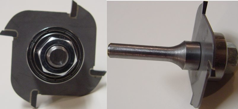
Tuesday, Nov 13 2001: T-Molding Extravaganza
The friendly neighborhood UPS delivery service left me a present today.... T-MOLDING and Router Bit!
Here's a picture of the router bit I bought from
t-molding.com:
IMAGE: T-Molding Groove Assembly (1/4" shank)
The caffeine ingested during work left me in a funk, so I wasn't originally going to
move to the next part, but my eagerness won out, and I cut the grooves in the
main panels anyway. Additionally, I had to take out the screws along the edges
so that I'd get a smooth groove, so I went ahead and countersunk all the screws on the
external panels. I still have to cut the groove in the control panel, but that
will have to wait until I've finished the wiring harness assembly:
IMAGE: T-Molding Groove, Countersunk Screws
|
|
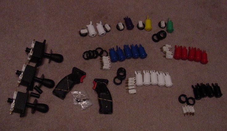
Monday, Nov 12 2001: CONTROLS ARE HERE!!
I got my Controls, FINALLY -and it only took 22 days from my initial order-. HAPP,
being so eloquently, themselves, has found it necessary to send me an invoice
(trying to bill me a second time
for the same set of parts). I guess I'll have to call and clear that up so they won't let
harass me if I try to
order anything else. Here's a pic of my Controls:
IMAGE: Controls (Complete!)
Since I haven't received my T-Molding and Router Bit yet, I decided to do some more
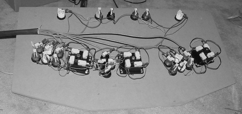
wiring. This time, I concentrated on the control panel attaching approximately
72 0.187 tab blade connectors (female) to the CAT5 cable that will connect to the D-SUB
mentioned yesterday. I'm not 100% happy with the way I connected all the grounds
(Serial blade connectors along 18 AWG solid core ground wire), but I've already done
the work, and I don't plan on changing it unless I run into some isolated ground loop
problems. PIC:
IMAGE: Control Panel with Controls and Wiring
|
|
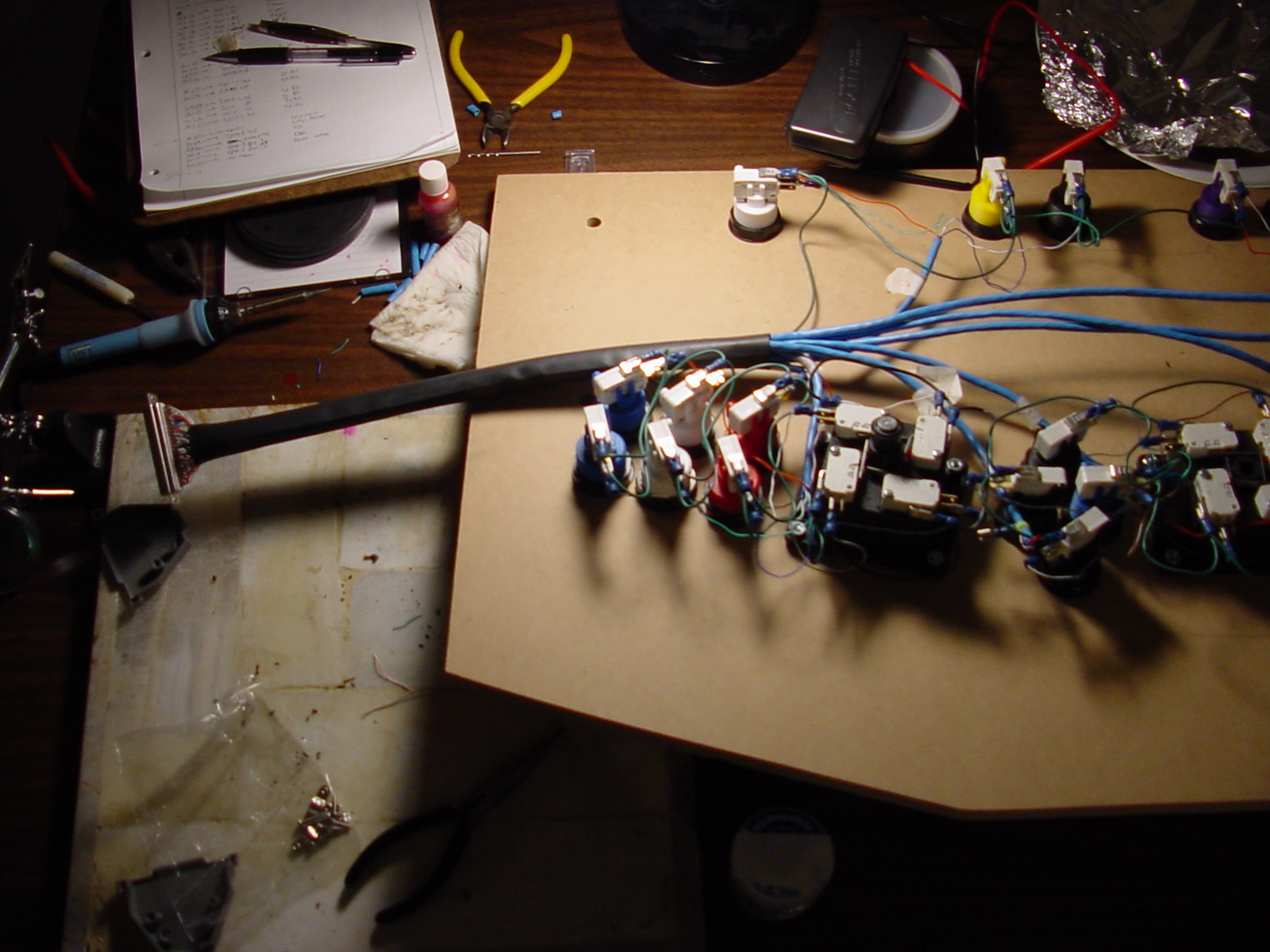
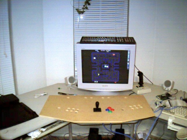
Sunday, Nov 11 2001: The Acid Test
Wiring! Lots and Lots of Wiring.. I got to a point where It was only
a stones throw from rigging up a test harness, and I could resist no longer:
IMAGE: Control Panel with Test harness and 4 way setup.... It WORKS!!
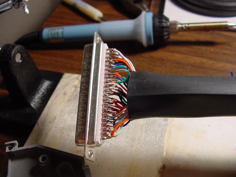
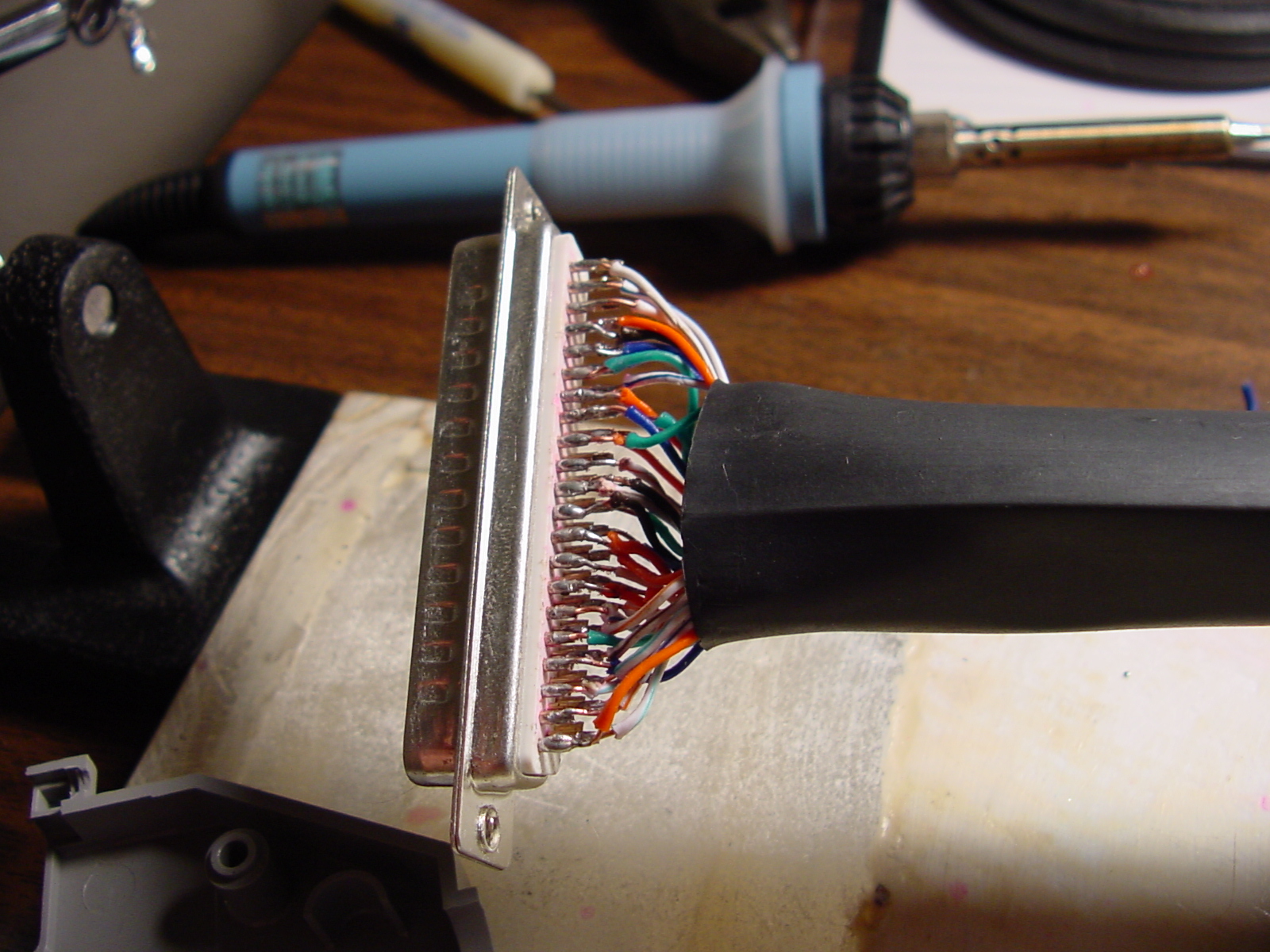
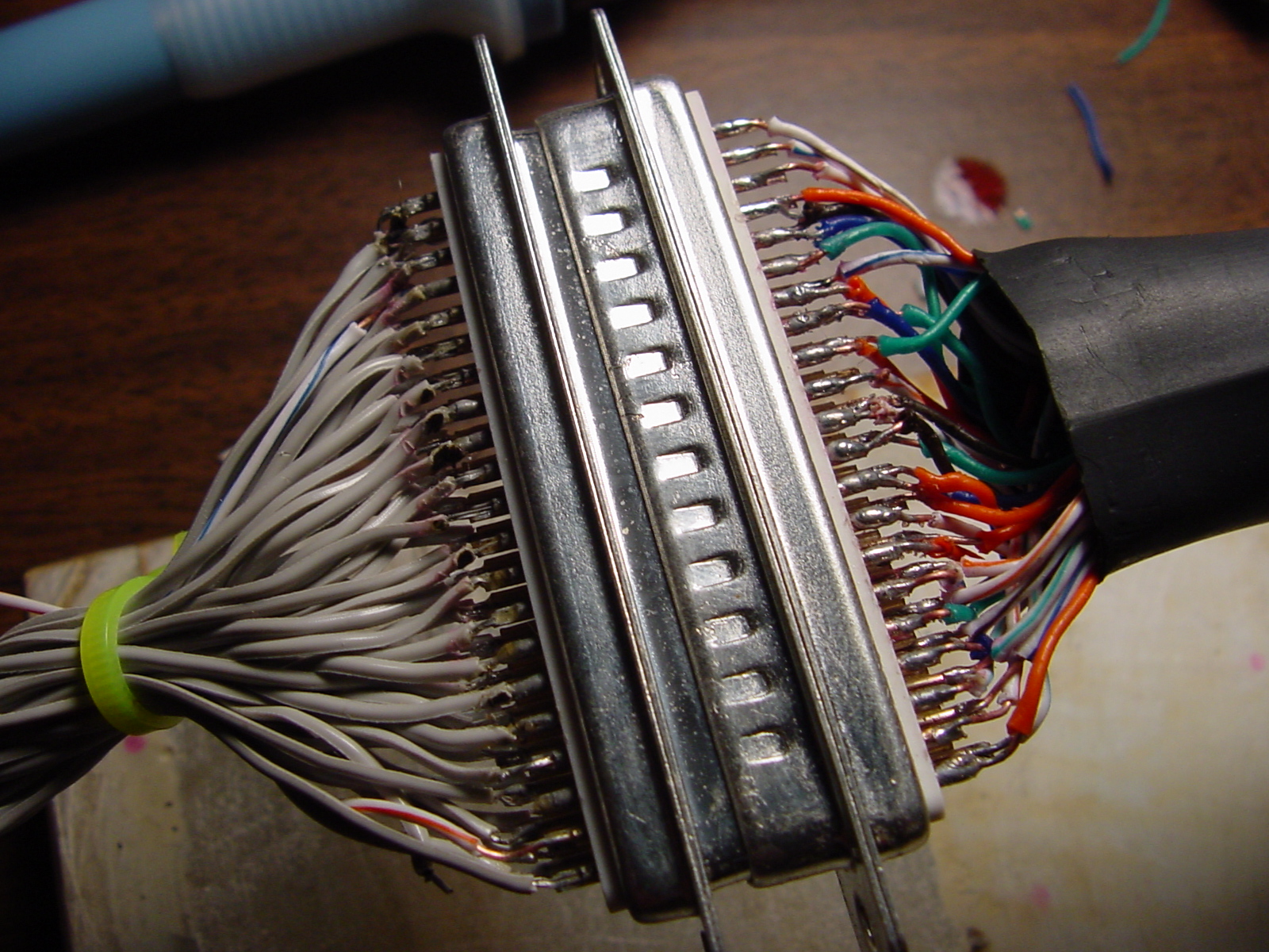
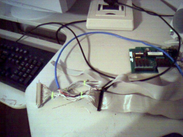
IMAGE: A closer view of the
Encoder side harness.
I chose a 62 Pin D-SUB connector for the encoder to control panel interface.
This will an adequate number of inputs on a single plug (while remaining
flexible enough to be plugged and unplugged many times without incident).
My soldering skills had deteriorated somewhat since college, but wiring up this
D-SUB was a good refresher.
[ed: My original design called for a single keyboard encoder that resided in
the control panel box with a wiring harness that allowed me to connect multiple
control panels easily. While this works well after complete, it creates a LOT of
extra work to build each new control panel. In retrospect, I probably should have
purchased an iPac from www.ultimarc.com for
each control panel that I was planning on building. then I would only have to wire
the controls to the an encoder attached directly to the control
panel. It would also have allowed a single PS2 cable to be used when plugging
in the control panel.]
|
|
Friday, Nov 9 2001: Back to Work!
I borrowed a router, and bought a 1/8th inch slotting bit, and was able to
cut a groove in a 3"x28" crossbeam which will be used to hold the plexiglass.
Additionally, I installed the control panel box support beam as well, and
drilled the hole for the coin door lock. Unfortunately, I didn't pay much
attention to the lock I purchased... It's exactly 5/8 deep which is the same
depth as my coin door, so lock installation will have to wait. I installed
some shelf brackets to the cabinet floor to give additional support (The
cabinet is quite sturdy without these, however). Here are some pics
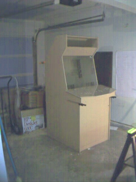
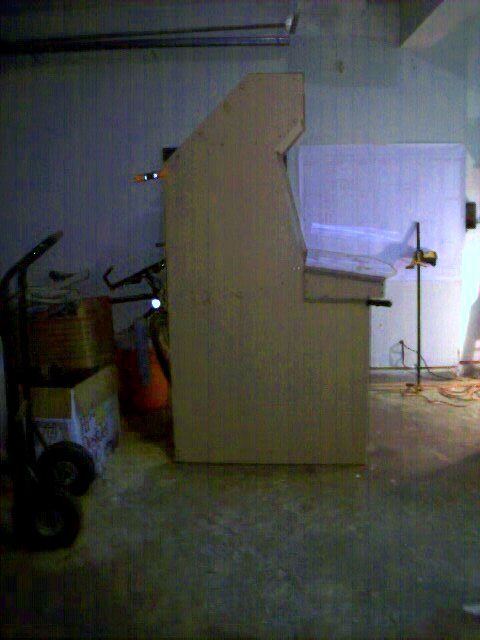
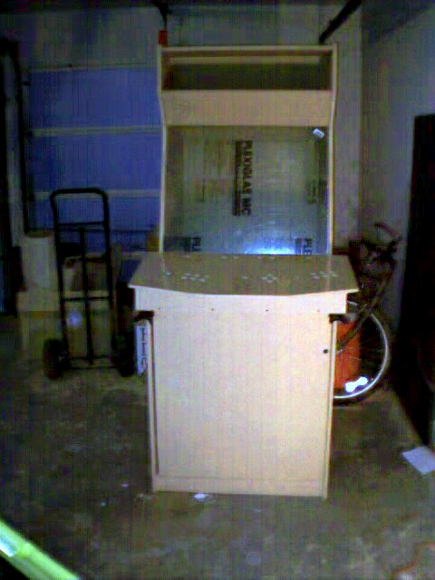
of the cabinet as it stands right now:
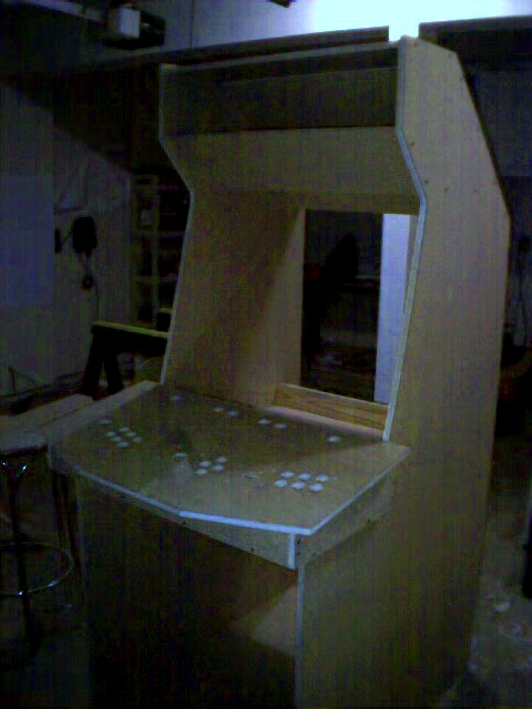
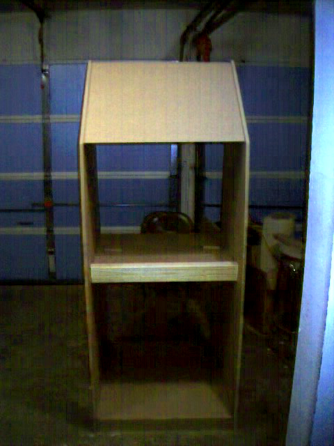
IMAGE: ANGLE 1 - Cabinet with control panel box
sitting on the cradle.
IMAGE: ANGLE 2 - Cabinet Monitor shelf and
monitor stop blocks installed.
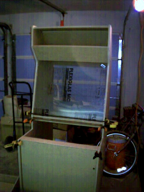
IMAGE: ANGLE 1 - Cabinet with Plexi and Coin
Door clamped on
IMAGE: ANGLE 1 - Cabinet with installed Plexi,
Control Panel box and Clamped Coin Door (Isometric View)
IMAGE: ANGLE 2 - Cabinet Side View
IMAGE: ANGLE 3 - Cabinet Front View
I'm Still waiting on my T-Molding and groove cutting Router bit from t-molding.com,
and controls re-order from HAPP.
|
|
Wednesday, Nov 7 2001: Stuck! (sort of)
I'm at the point that there's not a lot I can do on construction until
I get my T-Molding and groove cutting router bit from
t-molding.com.
Called HAPP, and found out that they'd been holding my order because
they were out of 1 Player Buttons (grrr). I asked if they would split
the shipment up.. She said yes. [It's now been 18 days since I originally
placed my order and I STILL don't have my complete order.]
Cut the second control panel plexi, and being a bit gun shy, stored it in
the kitchen for safekeeping.
I took a break from the construction for a bit and focused on how
to make a decent control panel overlay. BOY! Do I wish I had MAD Photoshop
Skillz! Anyway, I managed to eek out a prototype of the control panel
overlay... It can be viewed here:
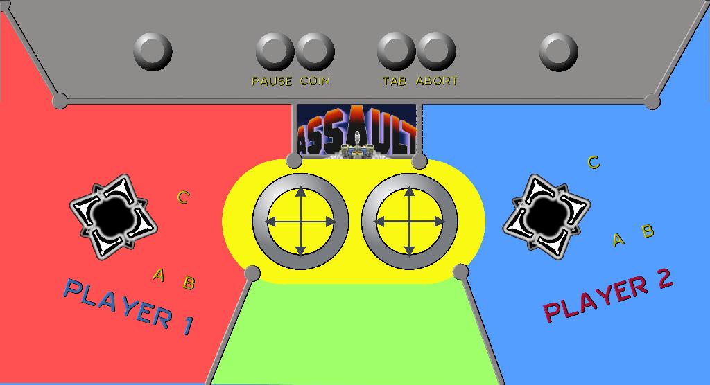
IMAGE: 1600x848 example version of Control Panel 1a overlay
(Down-scaled from 6800x3600 which was a whopping 5.5 Megs!)
I borrowed the images for the control sticks from
Oscar.
(NOTE: you probably don't want to print *THIS* version because it's got
outlines of the Autocad drawing on it, as well as the fact that it's the
FIRST control panel I designed and not the one I am using in my final
plans (the 4 way joystick is too low and there are only two buttons instead
of 4))
In any case, I will fix the images tomorrow and post a print quality
version of both Control Panel 1a and 1b (just for posterity).
|
|
Tuesday, Nov 6 2001: Reprise from Disaster
Today I didn't get much construction done, however I did
deviate from my original design a bit to implement a much more clean
way to mount the plexiglass for the monitor cover. Basically, it consists
two parts:
-
Adding a horizontal Shelf directly behind the bottom of the lower
marquee panel with a small 1/8"ish gap between the two for the plexi
to slide into
-
Adding a 3" horizontal support board directly behind the control panel box with
a 1/8" inch groove routed into the top (around 3/4 of an inch from
the front edge)
This modification will allow me to quickly slide the plexi up into the
top groove and let it fall back down into the notch below, remaining
secure by it's own weight. I'm glad I managed to come up with something
better, because I really didn't like the idea of using mirror supports
or similar hardware to hold it on. Additionally, this modification to
the design will allow me to use the new horizontal shelf as a speaker
placement behind the lower marquee panel (instead of having to mount
the speakers directly onto the lower marquee panel, as I had originally planned).
Finally, I discovered that the plotter I used to print my design plans
ALSO prints raster images (quite well as a matter of fact) so I was able
to print a full size marquee, and will be able to print a full size
control panel overlay later.
|
|
Monday, Nov 5 2001: GRRRR
Here's a quick list of how my day went astray!
- Installed the angled back, and top panels
- Stood the cabinet up
- Placed the control panel box on it's cradle to play test the height
- Got worried that I might mess up the control panel top (which still had the
pristine plexi attached)
- Placed control panel box, control panel top, and plexi on the ground so they wouldn't get
bumped off while I was screwing panels into the cabinet
- Watched in horror as a support board fell down to the ground onto..... you guessed it!
THE CONTROL PANEL TOP! (Basically, shattering the plexi that I'd spent one
and a half hours cutting and drilling.)
Oh well. I had another piece of plexi that I was saving for the second control
panel, so I suppose I can use that.
I would take some pics of today's progress. However, the camera is now in
the care of its owner so he can download the latest images I've taken.
|
|
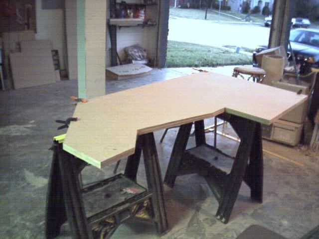
Sunday, Nov 4 2001: Wash/Rinse/Repeat
Today began with the final MDF panel (panel 2) which was sketched and cut out
(without incident).
I now have all my pieces together, so it's time to move onto making sure
they line up. I clamped the two sides together, and used a belt sander
to adjust the edges that didn't line up completely. Of course this can be done
by hand, but I wouldn't suggest doing it unless you have lots of time
and energy! Here's a pic of the clamped sides before sanding:
IMAGE: Cabinet Sides Clamped for Sanding
I also checked the width of all the cross pieces, but they were within
acceptable tolerances and thus didn't require any sanding (outside of
some general cleanup on corners).
Next, I diverted my attention to the Plexiglass for the control panel top.
One piece of advice here, If you are going to break your plexi edges, make
sure you score the plexi with a good scoring or box cutting tool
so that the
scored cut is around half the depth of the plexi sheet (1/16th inch for 1/8th plexi).
This will keep it from breaking unevenly (requiring obligatory sanding).
Here's the method I found worked best used to cut the edges and holes:
- Clamp the plexi onto the Control top panel and turn the over
so the plexi is on the bottom.
- Score overhanging edges and place scrap wood underneath
with plexi sandwiched between Control Panel and scrap wood.
Line up the edges and scrap wood so only overhanging plexi shows.
- Break along scored edges with even force along exposed plexi
- With same sandwich config as previous step (control panel on top, plexi
in the middle and scrap wood underneath the hole), use a hole saw with a
cental bit
to go through the same holes that exist in Control panel. Since the plexi
is sandwiched between two pieces of wood it won't ride up and cause
cracking or other undesired effects, so it's OK to run the drill in Forward at full speed.
(NOTE: It may help to clamp all three pieces together for this stage)
Here's a pic of the control panel plexi in it's finished state
(NOTE: protective tape still on, and there's sawdust everywhere so it
doesn't look perfect):
IMAGE: 1/8" Plexi Control Panel Top
Next, I went back to the Cabinet sides and propped them up with various
items around my garage, and screwed in the bottom pieces. I started
by laying the cabinet on its back and placing a 1/2 inch guide on the
ground between the sides that I could lay the Back kick plate on. getting
everything lined up for the first set of screws wasn't trivial, but maybe
I was just tired. Make sure all the screws on the edges are inset about 1/2
inch if you will be using a T-Molding bit to cut grooves on the edges.
After screwing in the back kick plate, I proceeded with front and back
floor panels and finally the front kick plate. Here's an image of what
it looks like after this work has been done:
IMAGE: Cabinet Bottom Attached
|
|
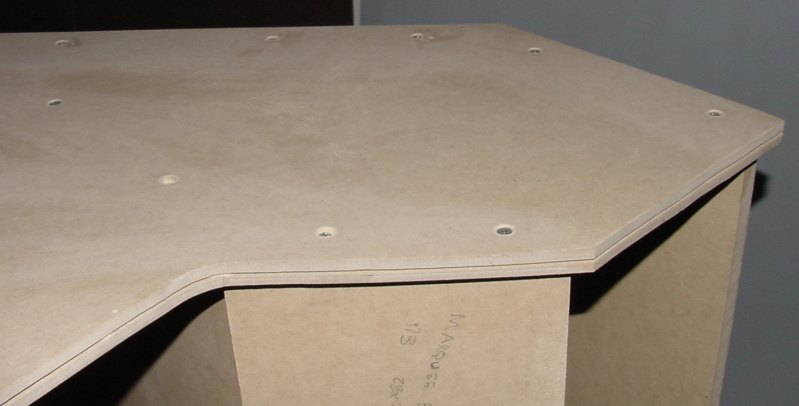
Saturday, Nov 3 2001: 12 Hours - FULL SPEED AHEAD
Not trusting my skills at squaring my lines with a small triangle and
yardstick, I ran to home depot and purchased a giant Construction Square ($9.97).
In retrospect, I would list this as a MANDATORY requirement, as most of the
lines I *thought* were straight were not. Plus it speeds up marking
operations.
Before I made any cuts, I double checked corners and lengths. Finally, I set
up my yardstick straightedge with the T-Square and clamped (or taped) it
down so that the circular saw would have a guide along the cut. This is
important if you drink lots of coffee, but still want straight cuts (Thanx to
CyberPunk for the idea as it saved a lot of grief).
A few tips of my own for this cutting stage that you might find useful:
- If you're going to Freehand a cut with the circular saw, hold open the
blade guard with your finger while making the cut. Otherwise, you might jiggle the
saw when the resistance of the guard is released as it swings completely
open.
- Definitely hold open the blade guard open if you're going to be making angled cuts.
- Go SLOW if you're using a jigsaw, and make sure the bevel angle doesn't
get perturbed (Mine is a cheapo so this was happening a lot, which would
tend to make an undesirable beveled cut).
- Don't allow the MDF pieces to fall to the cement, if possible.
This can cause the corners to get a thrashed, which requires sanding to fix.
- For the interior cuts on the Cabinet sides, (eg: Those that you cant
get at with the circular saw) I used the 2" hole saw to cut a hole at the
inside corner and then the jigsaw to cut the line. This is a much
better method than doing the so called 'plunge cut' with the jigsaw which
isn't precise.
I was able to cut out all the pieces on Panel 3 and Panel 1, as well as
assemble the control box, as well as cut the holes on Control Panel 1.
Here are some pics of today's work:
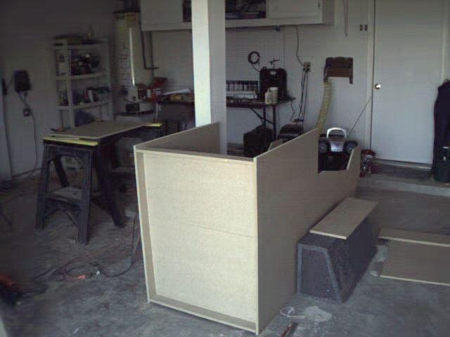
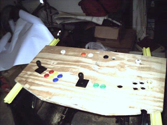
IMAGE: Angle 1 - Control Box (unconnected) with Prototype Panel 1
IMAGE: Angle 2 - Control Box (unconnected) with Prototype Panel 1
IMAGE: Angle 1 - Control Box (connected) with Final Panel 1
IMAGE: Angle 2 - Control Box (connected) with Final Panel 1
IMAGE: Angle 3 - Control Box (connected) with Final Panel 1
|
|
Friday, Nov 2 2001: Construction Begins!
Today, I bought the 3 sheets of wood. I originally considered plywood for my
base medium of creation, but several factors contributed to my decision
to go with Medium Density Fiberboard (MDF) instead:
- Highly Sanded plywood was Extremely expensive (on the order of $45-$50 a sheet)
- The MDF was quite a bit smoother and nice looking (unfinished) than even the best plywood
- MDF didn't have a natural bow.
- Finally seeing MDF *in person* dispelled the dirty image of particle board being flimsy and
un-trustworthy that I had in my mind.
It seems the only bad thing about the fiberboard was that it is VERY HEAVY.
After getting all the stuff home, I basically only cleaned up my garage and
penciled the lines on the first target MDF Panel (Panel 3 - Contains: the
Front and Back Doors, Control panel tops, and misc braces). After
completing these tasks I was tired so I quit for the day.
[ed: Check the
Downloads Page for plan Images and Autocad files.]
|
|
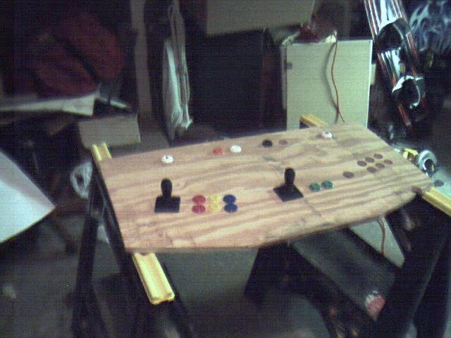
Thursday, November 1 2001: Getting restless
Knowing that I've been set back about 6 days from completion because of
the wrong HAPP order shipment, I became anxious to do something so I took
a scrap of Plywood and all my shiny new tools and created a prototype
Control Panel with the parts that were delivered to me yesterday:
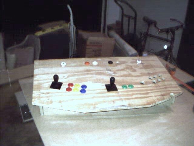
IMAGE: Angle 1 - Prototype Control Panel
IMAGE: Angle 2 - Prototype Control Panel
You can clearly see that they didn't even get close on the
button count as well as the joysticks being HAPP Universal instead of
Super. (I actually feel sorry for the poor sap whose order I got, because
these joysticks are HORRIBLE) [ed: In retrospect, if they simply swapped
our orders, I don't feel sorry for him at all! He ended up with much better
joysticks and a bunch of spare parts.]
Additionally, I've performed various scripting and programming tasks to
better integrate the Mame Frontend into my linux system (as of Mame 55.2
various capcom games no longer work, thus I have now the ability to choose
an emulator version based on the game being played. This should all be
seamless to the end user once I have gone through and checked all
the games.
|
|
Wednesday, October 31 2001: Progress and setbacks
At this point I have done the following:
- Finished the control panel (rev2) design
- Bought Tools and parts
- Created control panel layout diagram
- Created blueprints of the cabinet.
I got my controls from
HAPP Controls. However, the order was COMPLETELY wrong. I had ordered three joysticks, but only two
were delivered and they were 'Universal' instead of 'Super'. I was missing
approximately 13 buttons as well as other mistakes. I contacted HAPP and they
promised to re-issue my order.
I've spent approx 1200 dollars getting the necessary tools and supplies
together (and I haven't even bought the computer yet!!)
|
|
|
|
The Beginning
Incept Date: Sunday, OCTOBER 22 2001
This page is my attempt at gathering the details of a MAME
Cabinet Project 01 (MCP01). I will include as much info as possible
(pics and whatnot) to catalog the design, and construction of my
very own Mame cabinet! It will be laid out Journal style so if you read
it end to end, you will see my pitfalls and workarounds!
As of today, I have only designed and modeled ONE
of the many [ed note. many == 2] control panels.
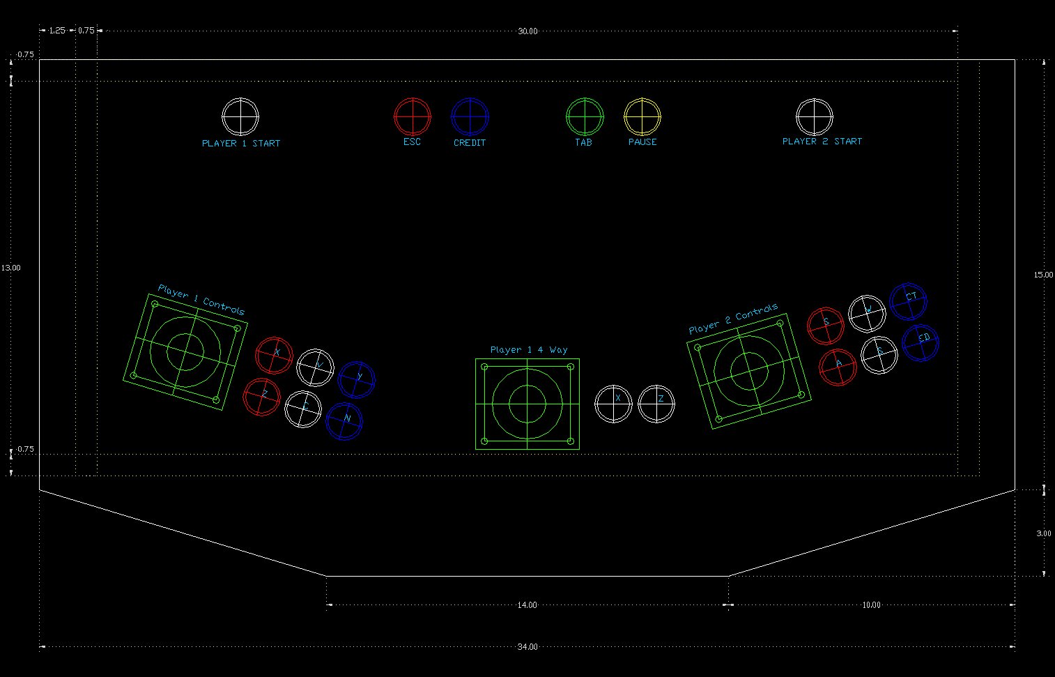
IMAGE: CPANEL1.JPG (to see
a large view of the Autocad in JPG format) This depicts CONSOLE 1
(A StreetFighter configuration + a 4 way Joy setup for Pacman/Defender
and the like. [ed: After two years of using this configuration, I would
recommend Moving the 'Esc'ape game and Add 'Coin' farther apart!]
FILE: CPANEL1.ZIP
(Autocad DWG Format)
For these plans, I reviewed many other works out there. I found none
of them exactly to my liking, for one reason or another, so I created my own
custom plans, drawing mainly from
Jeff's and
LuSid's.
|

|
|
|
|

Partslist
The parts purchased so far.
UPDATED! (1/2/04)

Gallery
Click here to look at a Gallery of my progress (all images seen in these
status reports in one place..)

Cryptnet
Click on this icon to return to
Cryptnet (My main Homepage)

Links
Click on this to see Links to
various other Mame/Cabinet Resources

Downloads
Click on this Icon for Downloads (Autocad blueprints of plans,
scripts etc... this section will evolve)

E-Mail
Click on this icon to send me some e-mail.
|
|
|